Wednesday 29 December 2010

First attempt at Turbo manifold


So, made some progress today on the manifold for the turbo.

It is basically the stock gsxr1100wp manifold stubs (including the bit that joins the head and the first bend). These are interference fit into 38mm tube (also in stainless). I cut these different bends from 135deg bends (3 of them), and then these all come together at a merge collector.

The picture shows it tacked up, and was to confirm that it clears the chassis rail (very important).

The nice thing about this design is that I only have 5 joints between pipes, and then the complex merge.

This is my first MIG welding project, so I expect to be doing a lot of grinding!


Tuesday 21 December 2010

2010 summary

Aimed to build a garage and sort out wood burning fire in living room.

Built a spanking engine out of old sidecar racing outfit parts. Kept engine in shed.

Took car on track-day to Abingdon. No grip, rubbish suspension, great fun, destroyed water pump but got home.

Became a school governor

Swapped old SVA engine for new engine. Fitted front ARB, stiffer springs, popped on ACB10's.

For the test drive, went to Llandow for track day (350miles in weekend). Met some great fold, awesome day, some oil surge, engine using oil (boo).

Bought accusump, changed gsxr600 throttle bodies to gsxr1000 throttle bodies and built a new airbox with secondary injectors.

Our sons learned to swim

Upgraded MS1 to MS2.

Modified MS software and built new hardware to allow stock gsxr trigger wheel.

Won 5 years funding for a project at work

Installed rear ARB

Started on the turbo conversion.

Aiming to sort out garage and wood burning fire in living room.

Tuesday 14 December 2010

post from new phone

So, I eventually got an android phone. Damn typing os a paon. Matt

Monday 29 November 2010

Turbo turned up


Turbo arrived.

Bit grubby but nothing broken and under all the grub its all rather nice.
1275663 Volvo 850 T5R 96-97 N2P23HT 49189-01350 TD04HL-16T-7CM2
This puts out 250bhp in the stock installation (2.3litre engine at 5400rpm).

Given that my engine is half the capacity (1.146) but revs to 2x5400 (11000rpm limit, although 11400rpm when the gsxr1100wp engine is installed in the Bimota SB6). It would appear that this turbo should be a great match.

Includes internal BOV (dump valve) that recirculates the air (no chav sounds).
Also includes internal wastegate. The actuator is an aftermarket item, which is a bit annoying, but it looks servicable. The actuator on this engine uses clever control so that the boost can be varied depending. This uses a pulse width modulated bleed valve. The stock actuator opens at 3-4psi, but the electronic control increases this to around 10-11psi. Not sure I can deal with the pulse width modulation from megasquirt, but the alternative is an after market bleed valve, so probably more straighforward to do it that way.

I still don't know how the BOV works, so will have to do some reading.

Next plan, get some flanges made up.

Saturday 20 November 2010

Turbo


There comes a time when too much becomes an alien concept.

So, I have decided to pop a little turbo onto my car. Probably a TB2809 (aka Nissan 200sx s14 turbo)

This will be limited to about 17psi boost (plenty), but should deliver 250bhp at 14psi (>500bhp/tonne). This is more than I want to be running, but leaves me with sufficient headroom for when I need to destroy tires.

I need to learn to weld for this project, and also a few other details, but it seems like a sufficiently foolish plan to be worth progressing!

Saturday 18 September 2010

Long tooth trigger wheel success


Just a quick note to say that my megasquirt now uses the stock suzuki trigger wheel and sensor, and runs!!!!

I've spent the week inventing electrical circuits (something I know nothing about) and generally burning myself with solder, and she runs.

Here is a picture of the circuit that I needed to build to condition the pulses.

Monday 13 September 2010

Triggering problems


My engine isn't at its best;

it is from a racing sidecar and has seen some rather extreme modifications!

All the counterweights have been removed from the crank!
The compression is around 16atm.

It is also a bit tired, and has been bored to 1146cc (about 7% over)

Finally, as it is tired not all cylinders share the same compression (these vary with temperature and things, but one is down as low as 10atm at the moment).

These things all add up to variable crank speed whilst cranking. It turns out that this us upsetting my EFI computer into worrying about losing the trigger on the missing tooth wheel.


There are loads of solutions to this (the best being to rebuild the engine so it works properly), but I decided to try to make the triggering more robust, and specifically, to use the stock suzuki trigger wheel (because that approach feels most "right").


Here is some progress (image at top of 'scope screen).


the bottom trace shows the signals from the VR (variable reluctance) sensor.

The top trace is the output from the electronic pre-filter that I have built. I am pretty pleased with this, as the MS2 can detect edges in this signal that are both positive and negative, and hence I am in a good position for the software to deal with this. Note also that the long tooth is about 10x the length of the short tooth, so it is pretty definitive.

Here is the output when I log the teeth using the MegaTuneStudio software.


Now I just need to build a wheel decoder. My first version didn't work, but I found a small (but critical) bug in this, so I am optimistic that I might be able to get the engine to fire tonight.

Wednesday 18 August 2010

Starting troubles

Ever since I have installed the Ms2 board I have had some problems starting the engine.


The characteristics are that if it doesn't start straight off, then it requires a bit of cranking. Sometime it hicups a bit. Once it kicks then heavy application of the throttle gets it going, but it isn't so nice. The battery is excellent, so that isn't the problem.

Not sure why, but the Ms2 has loads of nice tools for investigating this stuff. It seems (from the msextra forum) that the Ms2 is cleverer but consequently more temperamental.

I logged the trigger wheel which was interesting. Basically it is a 11 tooth wheel, one tooth every 30deg and one missing (a so called 12-1). This runs from the crankshaft (not the camshaft, which is why I run wasted spark ignition).

When running the time between teeth look like this:


This is exactly right, as the long gap is after the missing tooth, and all the other teeth are the same length. This works perfectly with the MS as it is looking for a gap that is more than 1.5x the length of the previous gaps, and then the gap after this long (missing tooth) gap must be 75% of the long gap. All syncs up nicely and everyone is happy.


But, what does it look like whilst cranking?


As you can see when it is cranking the gap between teeth varies through time. This is all to do with the forces required to compress the gas in the cylinders. Note there are a couple of things, firstly you can see the 4-stroke nature of the engine as alternate crank rotations have different profiles. I think this is because I have different compression on the frontmost cylinder, which results in the engine running a bit faster at that point.

Note also later on how the sync is lost (sync is the blue curve along the bottom, 1=synced, 0=no sync) after the engine fires. In this case the long gap is still seen but the gap after it is not.

The problems are due to the low inertia of this engine, the small number of teeth, and the high and variable compression. I already knew that I needed an engine rebuild, but here is more evidence.


Incidentally I ran a compression test.
12 16 10 12 (where 12 is the one that was previously down at 8). I don't know what is going on but I was already planning an engine rebuild so its not a big deal.

Tuesday 20 July 2010

MS2 upgrade

I upgraded the chip in my megasquirt from MS1 to MS2.

It is amazing what the programmers managed to get out of the MS1 chip, it was designed to run fuel injection, but with the megasquirt extra code, it runs ignition and fuel injection, this means that the timing precision required is around 100x more challenging (i.e. instead of a squirt or several per revolution, ignition requires precision of a degree or so per revolution).

I had been running into the limits of the MS1 chip for a while. It couldn't keep up with my 36-1 trigger wheel, so I converted the wheel into a 12-1 and it was fine, although sometimes the rpm went a bit funny at 10500rpm (perhaps the rev limit coming in early, not sure). Additionally I was limited with acceleration enrichment (you can do MAP or TPS based with MS1, but with MS2 you can blend the two). Next the TPS resolution was a bit of a problem with MS1, so I added a parallel resistor to improve the resolution at closed throttle positions. Finally, when I changed to secondary injection, then it was not possible to gradually ramp in the secondaries while the primaries ramp down. All in all it was time for a change.

So, Ms2 comes as a daughter card, which replaces the chip on the megasquirt board. You have to be careful to follow the instructions to the letter to avoid blowing it up. The megasquirt maps all need re-writing, but fundamentally much of this is copying from the old maps and settings.

After some messing around I managed to get the car running, and preliminary results suggest it to be much smoother and nicer. I think the ignition timing wasn't so good with the MS1, and injector timing is much better with the new chip.

Going for a 10minute drive sorted out the fueling map, so I am very pleased with it. Even on the tuning run where it was overfueling like mad (AFR of 10.5-11.0 when it should be 13 or so) it went very nicely. So I am very optimistic of how this is going to turn out.

Actually everything about it is awesome with no ned to reflash the memory to do things like updating the sensor scaling values (temp for example).

No pictures, sorry.

Thursday 15 July 2010

Civic injectors do fit


Just a quick photo of the GSXR and Honda Civic injectors. Only differences are the civic ones are 7mm longer, and the green tip is a bit larger. For the gsxr600 bodies the hole was large enough, for the gsxr1000 ones I needed to drill it out (annoying as an off the car job). The rubber gaskets are identical between the two injectors.

Codes on the injectors are 4109, and these are injectors from a D16Y7 civic coupe from 1998. Flow rate is 190cc/min, and opening times are 0.80ms with a 0.20ms/V sensitivity (according to www.injector-rehab.com), some claim flow of 180cc/min, all flow rates at 3ATM 43.9psi, which is something of a Suzuki/Honda standard.

Dull stuff, except if this is what you need to know!

I have a follower!!!

Welcome, Mr Ellershaw,

Never had a follower before, feels like a religious moment.

Tuesday 13 July 2010

De-stiffening the ARB; grinding, filing, sanding

I've been trying to workout what is going on with my anti-roll bar.

I put it onto the front of the car, and it certainly helped to make the car more stable in the corners. But, it gave me dreadful wear on the front outside tyre.

So, I hit the books to try to work out what was wrong.

ARB stiffness is a simple calculation,
Effectively the stiffness depends on the material properties, diameter to the power 4 (for hollow bars you do outer diam^4 - inner diam^4), divided by the length.

Then the effect that this has on the wheels can be determined. This has two parts, one the length of the arms on the ARB, and then the motion of the wheel versus the motion of the end of the arm. By this I mean, if the arm is short then it twists the ARB a lot for a small motion of the suspension. Conversely if the end of the arm is far from the wheel then the ARB will twist less than if the ARB is actually at the wheel.

The above arm and wheel motion ratio effects come in to the second power (once for the leverage effect which gives reduced force, and once for the fact that the angle is wound up less quickly and so it gets stiffer slower).

I'm not sure that explanation will help anyone, but who knows.

My bar is 16mm diameter and 400mm long and steel, with 5inch arms. Various calculations indicated that this was around 3times stiffer than ideal (determining ideal is the most difficult thing, but if you have a bar that is stiffer than everyone elses, and some of the everyone elses are winning races, then it means it is too stiff).

Welding ARB's gets a mixed reception as a method (mine is welded) so I didn't fancy making a new bar (if I did then I would use 2mm thing CDS tube of 1/2inch diameter, and get the ends mandrel bent, maybe bend them myself cold). So I decided to reduce the outer diameter of my bar.

Lots of grinding, filing, and sanding later I went from this red thing;


To this silver thing;


Going for a drive it felt like there was more flex at the front, but this will only come in for "on the limit" handling, which isn't appropriate on the road. The original bar had a stiffness of around 400lbs/in whereas the front springs are rated at 175lbs/inch, so it was like a solid front axle. The revised bar is more like 180lbs/inch. Exact calcs are more difficult, because there is a 70mm section of 16mm, then a 330mm section of bar that is between 12.5 and 13mm. (the calculation is to determine the stiffness of each section and then combine them as (1/((1/Q1) + (1/Q2))) the same as for parallel resistors.

Some software that I received from Tim Hoverd indicates that I should go softer still (maybe 120lbs/inch, although he does have stiffer springs on the front than I do).

Anyway, hopefully it is a move in the right direction.

Monday 5 July 2010

Staged injection, the search for smaller injectors

Most people are after larger injectors, that is injectors that inject more fuel. I have fitted 2 lots of injectors for each cylinder. The outer injector comes in once the air is flowing fast into the cylinder, the inner injector flows all the time.

In this configuration the fuel from the outer injector gets really nicely mixed with the air, and this also cools the air and so increases the charge density (the amount of air getting into the cylinder), both of these things are good for power.

THe problem is that my outer injectors are around 200cc/min, but the inners are around 270cc/min. The software expects the outers to be bigger than the inners and so......

So, I am hunting for smaller inner injectors. The injectors that I have are standard Keihin KN4 as supplied for GSXR motorcycles from 2000-2003 (gsxr600 all the way to gsxr1300 used these). I discovered that Keihin makes its money from supplynig Honda, and it turns out that Hondas of these eras also used these injectors (specifically the s2000, CRX, Odyssey and maybe others). So now I am hunting for a Honda with injectors smaller than 200cc/min. I found that Honda Accords have this style of injector (3 of these at a local breaker FWIW).

On this site it shows me what Hondas have small injectors:
http://www.accordinglydone.com/data/injectors.php

So I am after injectors from a Honda Civic CX with a 1.5 or 1.6litre non vtec engine. The problem is CX was only a US designation. Why is this so difficult!

Other useful pages
http://www.cadvision.com/blanchas/Ranger/AccelFuelInjectors.pdf

and
http://www.fuelinjector.citymaker.com/HONDA_FUEL_INJECTORS.html

I think I have enough information to work out which Honda part numbers relate to which flow rate, and so mayeb back to the Keihin part numbers. Not enough time to do it now though.

Radiator fans to Radiator fan

Power management is a bit of a problem on my car. The EFI system uses a lot, and the alternator supplies very little!

One problem was that with the fans running at idle the battery went flat. This meant that I didn't know what to do in heavy traffic. Stopping the engine would mean needing to restart (flatten battery), keeping the engine running would mean the fans running (flatten battery), and setting a higher idle would mean too much heat which would cause over heating.

I have been working on generating more power (new regulator), and using less power (HID and LED lights), and now I decided to address the fan.

Initially I had a single fan from a gsxr1000. This was not ideal and at the SVA things got a bit warm. So, I added a second gsxr1000 fan. This meant that the fans cycled on and off in the required manner and all seemed good. Total power draw from these fans was 10A, but in the old days of carbs I had enough to spare (I thought this, but it might not have been true).

To address the current problems, I tried the 2 fans in series, this dropped the current draw to 2.5A, but in this mode it couldn't cool the engine sufficiently such that the fans cycle on and off. Next I tried a single fan, but this was not juicy enough either.

Plan B, get a new fan. Went down to the scrappy in Berinsfield, and had a look. Specification was 12inch diameter, less than 4inches deep, and it needed to be a sucker (i.e. behind radiator). I looked at a few (tempted by the absolutely miniscule citroen AX fan) but ended up with a Mazda 323 fan, these cars have 2 electric fans, and this is the less powerful of the two.

Fits nicely with the Polo radiator, draws 5A (12A at startup, so 20A fuse needed), cycles on and off (on for about 90seconds before temperature drops, this was on a hot day, at 1200rpm idle).

Picture needed

Sunday 27 June 2010

Voltage Mk2

So, the bits arrived.

zx10r 2006 regulator is a FH010. The specification on this isn't clear but most people believe that these can generate 40-50amp. The great thing about these regulators is that instead of shunting spare volts to ground (and consequently wasting the power, and getting very hot in the process) I believe they switch the higher voltages on and off at a high frequency and the rapidly switched voltage looks like a smooth lower voltage. I think this is how it works (this is the same as a switched mode amplifier).

Anyway, on bikes that use alternators that include moving batteries the regulator/rectifier is an essential part. My alternator is more like a car one, the rotor carries a current (3 Amps, driven by the battery which I didn't include in my previous calculation) rather than magnets. The regulator in mine alters the rotor current so as to keep the voltage at 12v. This all makes good sense, but as noticed before it doesn't work so well for me.

So, I have removed the old regulator, and the old rectifier, wired up the rotor to 12v (non regulated), and fed the 3 phases of the alternator into the new FH010 regulator.

This is a new idea, but the logic is;
My problem isn't really different to the case with magnets, and these regulators work then.
This regulator should pump more current than the old one, as it can use the higher voltages from the alternator.
The old one didn't work, so hopefully this one will!

So far, it seems to re-charge the battery way quicker than the old alternator. At idle the battery charges EXCEPT when the lights and fans are both on. I tried dropping down to 1 fan (or 2 in series) and these were insufficiently powerful to cool the engine (it is 25deg C here at the moment, but that is no excuse).

More as it happens. The regulator runs nice and cool. I think this might turn out to be a great modification.

Secondary injectors working (sort of)


So, after all the wiring and plumbing the Secondary injection hardware was all in place.

I could have run this the other night, but I was a bit edgy about it all, so I left it for the weekend.

First run, much trepidation, set it to come in at 7.5k rpm. Drove along, and at 7.5k is just coughed and grumbled and coughed (note settings are 7.5k rpm, and manifold pressure (MAP) has to be above 80kPa). It felt like it was lean (rich was a possibility, but unlikely). Looking at the logs is turns out that the MS thinks everything is working, but the AFR (lambda probe) makes it clear that these is not enough fuel.

Tested polarity on injectors (doesn't seem to matter), tested injectors (fine), tested continuity from transistor in MS and the injector leads (FAIL). Basically I had wired the 37pin connector wrongly (dohhhh).

Test 2: drove out, and logged. I also put a video camera under the bonnet looking in through the window of the airbox. The idea is to see if the injectors are all working, and to see if the fuel is going in the right direction. Anyway it recorded for 10mins, and then shut itself down (damn just before the interesting bit!). Here is a log-file.

This log shows up a few things:
1) injector switch is working
2) injector switch doesn't happen over 25 cycles (as requested) but is instantaneous (this is a feature of the hi-res code, which I am investigating)
3) After both injectors come on-line the AFR jumps up by around 1 to 1.5units.
4) I need more fuel up the rev range (actually dangerously lean at 10k rpm).


re 3: I have told the MS that the primary injectors are 270cc/min (this seems to be a well-known number) and the secondaries are 294cc/min (cbr1000rr, number from internet), but there must be a problem. Could be:
a) injector values are not right
b) injector opening times are wrong (this comes into this in a complicated way)
c) the fuel isn't getting into the engine from the secondaries

Not sure what to do, but I will put VE table mapping points just before and just after the switch-over point and then the MLV tuning function can sort it out for me (cunning plan I thought).

The problem with fueling at the top end hopefully is because secondary injection really does buy power by pulling in more air, and causes good mixing. It may (on the other hand) be due to (a,b,c) or the fuel pump may have run out of capability.

All good fun.

Tuesday 22 June 2010

Charging

One problem with putting fuel injection into a car with an old bike engine is that the fuel injection and the car all draw more current than the bike needed, and hence the alternator can struggle to deliver adequate current.

For example, the alternator in the GSXR1100 normally drives:
1 fan (5A)
1 cdi (low current draw, 4A)
and some lights including
1 headlight 5A
1 tail light 0.5A


In the car this increases to;
2 fans (10A)
2 headlights 10A
2 tail lights 1.0A
1 fuel pump 3A

Going fuel injected changes this further to:
1 Lambda probe with heater (3A)
1 set of fuel injectors (3A)
1 ECU unit 1A
1 ignition drivers (3A)

So, to cut a long story short. With lights on even at motorway speeds the result is a battery that is flattened. This doesn't stop the car, but means it won't restart.

A solution needed finding.

I swapped the lights to HID versions which draw less power, and changed lights to LED versions. So that is a start, but its not yet enough. After a drive the fans flatten the battery, so I need to do something about both the fans (probably try them in series instead of parallel, which will drop the current draw to 2.5A from 10A).

After that the only thing left is to improve the alternator. It is a ND (NipponDenso) 25Amp unit (I believe) which works like a car one. Basically the rotor current is regulated, and the outputs from the 3 windings are rectified. This is probably a good design, but by using a regulator/rectifier from a later model bike (in this case the FH012 unit, as promoted on the very impressive http://www.triumphrat.net site (see this posting for more help with this http://www.triumphrat.net/speed-triple-forum/104504-charging-system-diagnostics-rectifier-regulator-upgrade.html). It isn't clear whether this will work, as their modifications are for bikes with magnet based alternators, but its got to be worth a try. This RR unit seems to be used on the ZX10r (2006 model) which is where mine came from.


Monday 21 June 2010

Air temperature problems


I noticed that the VE values (amount of fuel required for correct air-fuel-ratio) is different at night versus the day time. There are two possible reasons for this: voltage (lights on at night), or temperature. Generally when the weather is warm (extreme was the Abingdon track day where air inlet got to 52degC) the engine runs lean. This is the opposite of what might be expected and indicates that the ECU is correcting for temperature but over-doing it.

The view is that I have a problem with heat-soak into the sensor. Basically instead of the sensor measuring the air temperature it measures the air-box temperature. This isn't aided by the fact that my airbox is a chunk of aluminium behind the radiator. So, when the air-speed is high the air is much cooler than expected (and so denser) and hence the AFR is too high (which could cause engine damage if not sorted).

The gsxr600 sensor (from 2001-2003) is a solid brass affair which takes ages to warm/cool. This is not the best, and more recent sensors (especially for turboed engines) are designed to have low thermal mass.

I made a sensor based on a gsxr600 mechanicals, and maplin thermistor and some epoxy filler.

I recalibrated the ECU for this new sensor (resistance values in photo) and it seems to work fine. Note: don't try to upload to the Megasquirt unless your battery is putting out a decent number of volts.

I am keen to get tuning again and hopefully the AFR will be nice and stable.

RAM air seen


I have connected up the air inlet, and finally got around to trying the car out.

After initial messing around with TPS (different range on this one than my old one so) I had to re-write the tables.

Starts on new TBI's and runs. Very exciting. Ran around a bit collecting logging data. Updated tables and repeated a couple of times. I had done this already, but it hadn't been running so well. This time around I had changed the inlet rubbers from the short ones (the same as 4x of the 1&4 ones on a gsxr750) to the long ones from that same engine.

A few interesting results. Firstly, now the air hose is more rigid and the trumpets longer the VE values are a lot higher (maybe 10%). Not sure which is the source of this, but who cares.

The interesting detail in the plot above is in the MAP (manifold air pressure) in 2nd 3rd and then 4th. Note that as the speed increases the MAP increases (at the same RPM). The pressure increase is bugger-all, but that is the problem with RAM air, you don't get much at normal speeds. At least the little that is available is working for me.


Saturday 5 June 2010

New Throttle bodies in


Very excited, fitted new throttle bodies and air box, and went for a start-up.

It started first time (a bit of a first for me), and seemed to run on the old map reasonably well.

TPS settings were different from previous TBI's (that was a custom mount so as to get the ideal TPS range, which I haven't done with these ones).

Stuttering when accelerating at low RPM, probably need to balance the carbs (I only did a static balance, i.e. put a drillbit in the gap and adjust so they all fall out at the same time).

Also the air hose inlet was flopping around at the front of the car, so that needed sorting.

So I built an inlet ram pipe thing. From a Maplin woofer trumpet (£2.69) and a bit of bent ally. O.D. on this is just less than 3inch, so perfect fit to the 3inch hose.

Not much of a photo (taken with the built-in webcam on the netbook).

Now I need to rivet this on, and connect it up. This is slightly messy as the hinging bonnet makes this a bit messy as the hose changes length as the bonnet opens, but it should be alright.

Sunday 30 May 2010

A weekends airbox building


I spent the whole weekend building an airbox. It isn't obvious how to build an airbox. Lots of talk on forums but generally it is a bit of a mystery. Lots of talk about how the manufacturers must have got it perfect (because of budget). But actually they have some pretty serious restrictions (size for example). In the case of the gsxr1100 airbox, the design isn't of a very complicated design. It is designed as a Helmholtz resonator with an inlet of 50mm diameter, and 57mm length, although I am not sure about the volume. Further the flow to cylinders 1 and 4 is restricted a bit by the location of the frame.

Finally, I want to try secondary injection having those injectors in the air box firing down the trumpets. The idea is that injecting the fuel earlier allows it to mix up really well with the air, and also it extracts some heat from the air, which increases the charge density (cool air is denser than hot air). The net effect is that more oxygen gets into the cylinder, and also the fuel that is there is really nicely mixed up. Allegedly this is worth 5% bhp, and it popular on the latest sport bikes (cbr1000rr for example) and as it adds cost clearly they believe it worthwhile.

The result of all this meandering is that I need an airbox that won't burn, or dissolve in petrol.

Also I am keen to boost the airflow.


Requirements were:
Decent volume (>8 litres is an Andy Bates recommendation that I have read)
Cold air feed with diameter of 75mm
Interface to gsxr1000 TB's
Fits under bonnet!
Metal and not flammable
Mounting for secondary injectors
Manufacturable by me

So here is the design (made in cardboard)


And a few hours (and hours) later.


And finally fitted in the car. Its all a bit WW2 fighter control but I like it. The reason for the plexiglass window is so that I can see what is happening with the secondary injection (where is the fuel going).


I need to work out how to layout the pictures in this!!!!

Wednesday 26 May 2010

Air box improvements and knackered engine

Bit of a discovery;

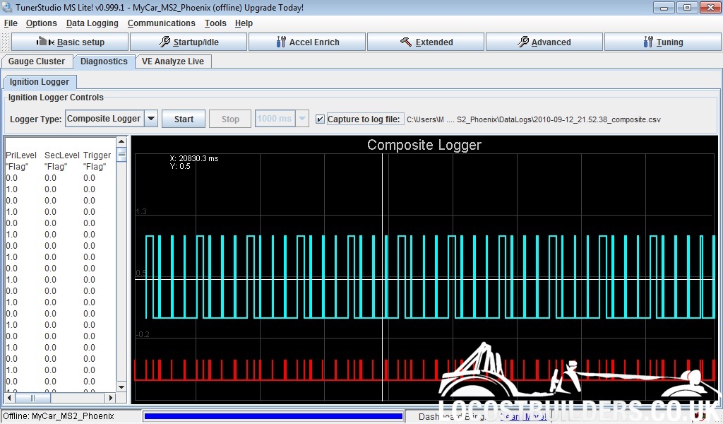
Old engine airbox on, no pipe connected to it, MAP pressure maximum of 96 drops to 93 at 10300 and full throttle.

New engine
with the airbox on an the pipe connected to it, the MAP pressure has a maximum of 96, as the revs rise at full throttle this drops to 91 at 10300 (drop of 5)

with the airbox off, but filter still in place. The pressure starts at 98 and drops to 95 at 10300 (a drop of 3)

Need to connect the airbox up, but remove the pipe, just to confirm that this drop isn't due to the pipe

It could be the pipe, or the back of the airbox.

With the back off the box I got loud aggressive noises at 5-6krpm, but it felt strong, the AFR wasn't particularly high, so although it felt strong it might not be getting much more air.


BUT, if I am getting a 2kPa drop from the bits between the trumpet and the map sensor take-offs, then I must be getting a further 2kPa (at least) from the more restrictive gsxr750 inlet rubber bits.

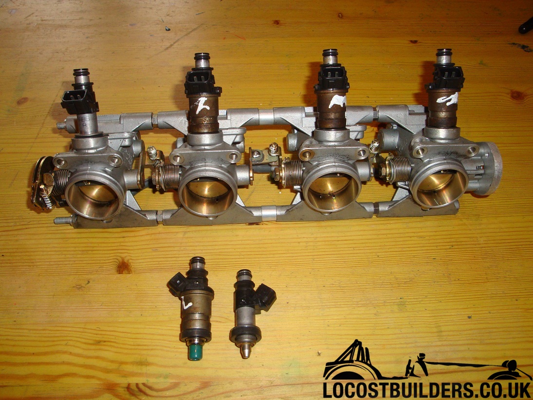
So, if I change to gsxr1000 Throttle bodies, I should lose some of the 2kPa, and also gain a further few kPa from the inlet rubbers. This should take better advantage of the porting that has been done to this head, and maybe release the big power.

I think this engine should be worth 180bhp (which is the limit of the injectors) with the bits that I have if I can set it up correctly.


Engine status update.
I have been losing oil since the rebuild, maybe 3litres in 300miles, and it isn't a leak as the rear right tyre (next to exhaust) was very very grubby. I had hoped that it was a combination of overfilling (with oil) and the engine breathing into the air-box. Also the bores were freshly honed, and this can cause some oil loss (I am a dreamer).

Anyway, I measured the compression on the engine. 8, 15,15,15 (all in atmosphere) so the front cylinder is down. Either damaged bore, damaged rings, head gasket or leaking valves. Measured the valve gaps, and it isn't leaking valves. I measured the compression after building the engine, and it was fine, so a ring wasn't broken on installation. It gets worse as the engine warms up (I think, although I haven't checked compression with a hot engine) but the oil would get thinner and so leak more easily.

Basically I need to sort the engine, which probably means a new set of barrels (the current ones are overbored to the maximum, so nowhere to go). Three choices:
1) go back to the 1074cc barrels, and pistons (stock)
2) rebore the 1074cc pistons and get new rings and head gasket (£300) to go back to 1146cc
3) purchase the a big bore Wiseco kit and rebore the 1146cc damaged barrels up to 1198cc. More power!!!!

This way I can built up a new 1198cc engine with a crankshaft that keeps the balancing weights. I can then transfer the special head over with the gsxr1000 Throttle bodies.


I need some more pictures!

35W my arse

35W HID drawing too much current

So, as a follow-up,

The rear lamps suggested by Razman turned up and they are excellent. I had tried some other ones, but to be frank the brake lights were inviting an accident. Razmans ones are the business (shipped from China, so not that quick).

The front sidelights turned out to be nice little units (and cheap).

So, the sidelights (from and rear) now draw 0.5A. This is down from around 2A. Also the break lights are still good, and the sidelights are actually a bit brighter FWIW. So all good there.


The HID kit arrived. I ordered a 35W, 6000K set, in bi-xenon H4. This uses a solenoid to move a shield to switch between high and low beam. Took a few days to arrive (China again), was a bit cheap and nasty when it arrived, but it was cheap (£46 including shipping and everything). No instructions (which may have been because it was opened in customs, or maybe because its crap. So, doing an install when you know the thing can generate 30kV with no instructions (at least it wasn't raining yesterday).

Installed it over the last couple of evenings (not made easier by having no earthing points on the glassfibre bonnet) and some of the wiring (the little connectors to the solenoids for dip/main) are of poorer quality than the rest of the kit, which isn't too awful.

Disappointingly, it isn't plug and play. I had to run a power lead back to the battery (the start-up currents are very high). So 20-40 mins, was really about 3-4hours. once holes had been drilled and all the bits mounted.

So, fired them up and they are nice and bright, but not evil. Also I took the opportunity to adjust the beam (one was a bit low). All good so far.

Then I measured the current.

7.7A on dipped (46W), 8.4A on main beam. THere is a further 0.1A going into them from another line (probably powering some control circuitry).

Now, call me a pedant, but 35W x 2 at 12V is 6A. The whole point of this exercise was to drop the current, so I have saved 1.5A when I was expecring to save 3.5A. I am sure that most people don't care about an Amp here or there, but I do.

The chap (dizaa8) is going to get some questions from me and likely a negative feedback if he can't sort it out, I am sure he will think I am mad, but I can't be sending them back (£37 postage is what he charged, £9 for the item) and messing around.


Hmm, maybe I will move to a blogg format for my kit-car diary.

The talktalk one is a bit pants.

I wonder if this supports pictures;