Aimed to build a garage and sort out wood burning fire in living room.
Built a spanking engine out of old sidecar racing outfit parts. Kept engine in shed.
Took car on track-day to Abingdon. No grip, rubbish suspension, great fun, destroyed water pump but got home.
Became a school governor
Swapped old SVA engine for new engine. Fitted front ARB, stiffer springs, popped on ACB10's.
For the test drive, went to Llandow for track day (350miles in weekend). Met some great fold, awesome day, some oil surge, engine using oil (boo).
Bought accusump, changed gsxr600 throttle bodies to gsxr1000 throttle bodies and built a new airbox with secondary injectors.
Our sons learned to swim
Upgraded MS1 to MS2.
Modified MS software and built new hardware to allow stock gsxr trigger wheel.
Won 5 years funding for a project at work
Installed rear ARB
Started on the turbo conversion.
Aiming to sort out garage and wood burning fire in living room.

Building, rebuilding and running of my Sylva Stuart-Taylor GSXR1100wp engined Phoenix kit-car
Tuesday, 21 December 2010
Tuesday, 14 December 2010
Monday, 29 November 2010
Turbo turned up

Turbo arrived.
Bit grubby but nothing broken and under all the grub its all rather nice.
1275663 Volvo 850 T5R 96-97 N2P23HT 49189-01350 TD04HL-16T-7CM2
This puts out 250bhp in the stock installation (2.3litre engine at 5400rpm).
Given that my engine is half the capacity (1.146) but revs to 2x5400 (11000rpm limit, although 11400rpm when the gsxr1100wp engine is installed in the Bimota SB6). It would appear that this turbo should be a great match.
Includes internal BOV (dump valve) that recirculates the air (no chav sounds).
Also includes internal wastegate. The actuator is an aftermarket item, which is a bit annoying, but it looks servicable. The actuator on this engine uses clever control so that the boost can be varied depending. This uses a pulse width modulated bleed valve. The stock actuator opens at 3-4psi, but the electronic control increases this to around 10-11psi. Not sure I can deal with the pulse width modulation from megasquirt, but the alternative is an after market bleed valve, so probably more straighforward to do it that way.
I still don't know how the BOV works, so will have to do some reading.
Next plan, get some flanges made up.
Saturday, 20 November 2010
Turbo
There comes a time when too much becomes an alien concept.
So, I have decided to pop a little turbo onto my car. Probably a TB2809 (aka Nissan 200sx s14 turbo)
This will be limited to about 17psi boost (plenty), but should deliver 250bhp at 14psi (>500bhp/tonne). This is more than I want to be running, but leaves me with sufficient headroom for when I need to destroy tires.
I need to learn to weld for this project, and also a few other details, but it seems like a sufficiently foolish plan to be worth progressing!
Saturday, 18 September 2010
Long tooth trigger wheel success

Just a quick note to say that my megasquirt now uses the stock suzuki trigger wheel and sensor, and runs!!!!
I've spent the week inventing electrical circuits (something I know nothing about) and generally burning myself with solder, and she runs.
Here is a picture of the circuit that I needed to build to condition the pulses.
Monday, 13 September 2010
Triggering problems

My engine isn't at its best;
it is from a racing sidecar and has seen some rather extreme modifications!
All the counterweights have been removed from the crank!
The compression is around 16atm.
It is also a bit tired, and has been bored to 1146cc (about 7% over)
Finally, as it is tired not all cylinders share the same compression (these vary with temperature and things, but one is down as low as 10atm at the moment).
These things all add up to variable crank speed whilst cranking. It turns out that this us upsetting my EFI computer into worrying about losing the trigger on the missing tooth wheel.
There are loads of solutions to this (the best being to rebuild the engine so it works properly), but I decided to try to make the triggering more robust, and specifically, to use the stock suzuki trigger wheel (because that approach feels most "right").
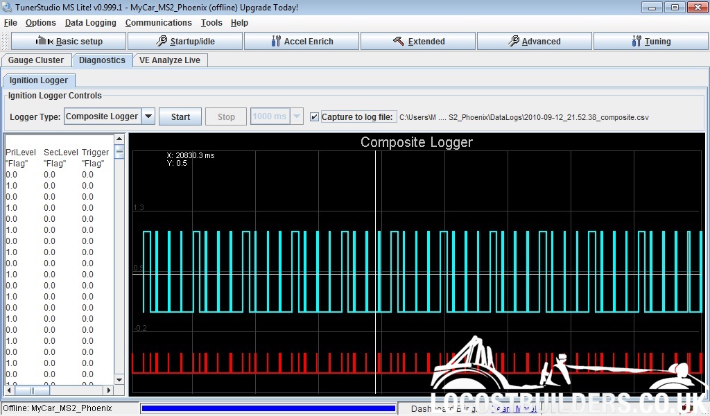
Here is some progress (image at top of 'scope screen).
the bottom trace shows the signals from the VR (variable reluctance) sensor.
The top trace is the output from the electronic pre-filter that I have built. I am pretty pleased with this, as the MS2 can detect edges in this signal that are both positive and negative, and hence I am in a good position for the software to deal with this. Note also that the long tooth is about 10x the length of the short tooth, so it is pretty definitive.
Here is the output when I log the teeth using the MegaTuneStudio software.
Now I just need to build a wheel decoder. My first version didn't work, but I found a small (but critical) bug in this, so I am optimistic that I might be able to get the engine to fire tonight.
Wednesday, 18 August 2010
Starting troubles
Ever since I have installed the Ms2 board I have had some problems starting the engine.
The characteristics are that if it doesn't start straight off, then it requires a bit of cranking. Sometime it hicups a bit. Once it kicks then heavy application of the throttle gets it going, but it isn't so nice. The battery is excellent, so that isn't the problem.
Not sure why, but the Ms2 has loads of nice tools for investigating this stuff. It seems (from the msextra forum) that the Ms2 is cleverer but consequently more temperamental.
I logged the trigger wheel which was interesting. Basically it is a 11 tooth wheel, one tooth every 30deg and one missing (a so called 12-1). This runs from the crankshaft (not the camshaft, which is why I run wasted spark ignition).
When running the time between teeth look like this:
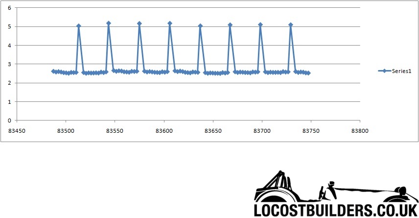
This is exactly right, as the long gap is after the missing tooth, and all the other teeth are the same length. This works perfectly with the MS as it is looking for a gap that is more than 1.5x the length of the previous gaps, and then the gap after this long (missing tooth) gap must be 75% of the long gap. All syncs up nicely and everyone is happy.
But, what does it look like whilst cranking?

As you can see when it is cranking the gap between teeth varies through time. This is all to do with the forces required to compress the gas in the cylinders. Note there are a couple of things, firstly you can see the 4-stroke nature of the engine as alternate crank rotations have different profiles. I think this is because I have different compression on the frontmost cylinder, which results in the engine running a bit faster at that point.
Note also later on how the sync is lost (sync is the blue curve along the bottom, 1=synced, 0=no sync) after the engine fires. In this case the long gap is still seen but the gap after it is not.
The problems are due to the low inertia of this engine, the small number of teeth, and the high and variable compression. I already knew that I needed an engine rebuild, but here is more evidence.
Incidentally I ran a compression test.
12 16 10 12 (where 12 is the one that was previously down at 8). I don't know what is going on but I was already planning an engine rebuild so its not a big deal.
The characteristics are that if it doesn't start straight off, then it requires a bit of cranking. Sometime it hicups a bit. Once it kicks then heavy application of the throttle gets it going, but it isn't so nice. The battery is excellent, so that isn't the problem.
Not sure why, but the Ms2 has loads of nice tools for investigating this stuff. It seems (from the msextra forum) that the Ms2 is cleverer but consequently more temperamental.
I logged the trigger wheel which was interesting. Basically it is a 11 tooth wheel, one tooth every 30deg and one missing (a so called 12-1). This runs from the crankshaft (not the camshaft, which is why I run wasted spark ignition).
When running the time between teeth look like this:
This is exactly right, as the long gap is after the missing tooth, and all the other teeth are the same length. This works perfectly with the MS as it is looking for a gap that is more than 1.5x the length of the previous gaps, and then the gap after this long (missing tooth) gap must be 75% of the long gap. All syncs up nicely and everyone is happy.
But, what does it look like whilst cranking?
As you can see when it is cranking the gap between teeth varies through time. This is all to do with the forces required to compress the gas in the cylinders. Note there are a couple of things, firstly you can see the 4-stroke nature of the engine as alternate crank rotations have different profiles. I think this is because I have different compression on the frontmost cylinder, which results in the engine running a bit faster at that point.
Note also later on how the sync is lost (sync is the blue curve along the bottom, 1=synced, 0=no sync) after the engine fires. In this case the long gap is still seen but the gap after it is not.
The problems are due to the low inertia of this engine, the small number of teeth, and the high and variable compression. I already knew that I needed an engine rebuild, but here is more evidence.
Incidentally I ran a compression test.
12 16 10 12 (where 12 is the one that was previously down at 8). I don't know what is going on but I was already planning an engine rebuild so its not a big deal.
Subscribe to:
Posts (Atom)