This was confirmed when the new buyers of the Phoenix project took their demonstrator to MIRA (http://www.jpsc-online.co.uk/viewtopic.php?f=4&t=594&hilit=mira#p3721 ). To cut a long story short they found lift above 50mph.
Additionally all the race Phoenii run with some kind of splitter/air dam at the front which is found to be beneficial.
One of my reasons for altering the bonnet hinge mechanism was to allow some space for an air dam. The problem before was that an air dam would prevent the bonnet opening as the way it pivots was not ideal. The bonnet used to hit the ground far too easily even without any additions.
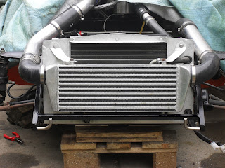
Finally, after changing the pivot I had to remove a section of the underside of the bonnet return, this was probably spilling air out the bottom that should have been going through the intercooler.
So, given all of that I decided that a splitter was in my future. I already have a complete flat bottom [years of training and careful eating ;-) ]. So according to the words I have read on aerodynamics a splitter/dam will negate the lift, and maybe buy me some downforce.
Construction was from 9mm plywood, with a steel frame. All painted satin black. The front edge is rounded and the angle is slightly up from horizontal (higher at the front). The lower edge of the splitter it 18mm below the flat floor and the gaps between the splitter and the region where the bonnet angles up (around the front wheels) have been filled. The total width of the splitter is 1220mm (standard dimensions for plywood, an extra 150mm might have helped, but this might be just a prototype). There have been some interesting recent articles on splitters in the FREE "track driver magazine" (http://www.trackdriver.com/ezine_subscription.php) and I have attempted (in general terms) to take on this guidance.
Anyway here are some pictures.
The raised section at the rear (right hand side in this picture) sits under the existing flat floor. The cut-out (fairly central) is for the tow loop.
My sons (Top Gear experts) think it looks good, so that is positive. Personally I am a bit worried that its a bit Max Power, but I'm prepared to see whether it grows on me.
Went for a test drive along our road, which has massive speed cushions. These are the full 100mm (100mm is the legal maximum) and only across the middle of each lane. I taped on bits of cardboard under the splitter. On my return only bits of cardboard less than 15mm remained!
My test drive did seem to indicate that the front end is a bit more planted. I say this based on feel alone, and to be honest I have found cars to drive way better after washing them or giving them a vacuum, so I don't think my assessment means much.
Anyway its been a nice little project and it seems to work. The only problem that I ran into came from the known asymmetry of the phoenix body (they are all like that sir) which resulted in the front right rubbing against the vertical section. I attacked it with and angle grinder (abrasive flappy wheel thing) and re-painted, need to check again tomorrow to see if that has sorted it.


